


HK-SFP-1.25G-20-1550

 Opis
Opis
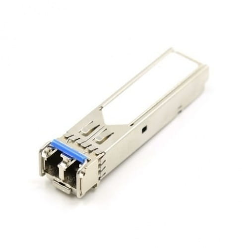
Wkładka SFP, TX1550nm/1.25G, RX1310nm/1.25G, LC, jednomodowy, pojedyncze włókno, zasięg 20km, 0-70st.C...
Gwarancja: 36 mies.
Karta katalogowa 
Tekstowa zawartość karty katalogowej PDF:
1.25Gbps Single Mode BIDI SFP Transceiver
HK-1.25G-20-1310
-1-
Features
a. Single Power Supply 3.3V
b. Small Form Factor Pluggable (SFP) MSA Compatible
c. Single Fiber Bi-Direc tion LC Connector
d. Hot Pluggable Capability
e. Compliant With ROHS Standard
Applications
a. Fiber Channel
b. Gigabit Ethernet
c. Switch to Switch Interface
Absolute maximum ratings
Parameter Symbol Min. Max. Unit
Storage Temperature T
S
-40 +85 ℃
Supply Voltage V
CC
-0.5 +3.6 V
Voltage at any Input Pin V
IN
0 Vcc V
Power supply current I
CC
- 300 mA
Recommended Operating Conditions
Parameter Symbol Min. Typ Max. Unit
Operating Temperature
T
op1
0 - +70
℃
T
op2
-40 - +85
Supply Voltage V
CC
3.1 3.3 3.5 V
Data Rate - - 1250 - Mb/s
Operating Conditions
TransmitterT=25℃, V
CC
=3.1~3.5V)
Parameter Symbol Min. Typ. Max. Unit
Central Wavelength λ
C
1280 1310 1360
nm
1480 1490 1500
1520 1550 1580
Spectral Width Δλ
DFB@-20dB - - 1
nm
FP@RMS - - 3
Output Power Po Reference Ordering Information
Extinction Ratio ER 9 - - dB
Differential Input
Voltage
V
DIFF
500 - 2400 mV
TX Disable Input
Voltage Low
TX_DISABLEL 0 - 0.5 V
TX Disable Input
Voltage High
TX_DISABLEH 2.0 - V
CC
V
1.25Gbps Single Mode BIDI SFP Transceiver
HK-1.25G-20-1310
-2-
Transmit Fault
Output Low
TX_FAULTL 0 - 0.8 V
Transmit Fault
Output High
TX_FAULTH 2.0 - V
CC
V
Eye Diagram Compliance with ITU-T G.957
Receiver T=25℃, Vcc=3.1~3.5V)
Parameter Symbol Min. Typ. Max. Unit
Wavelength Range
λ
1260 1310 1360
nm
1480 1490 1500
1520 1550 1580
MIN. Input Power
(Sensitivity)
10/20KM
P
MIN
- -
-21
dBm
30/40KM
-24
60KM
-26
MAX. Input Power (Saturation)
P
MAX
-3 - - dBm
Signal Detect-Asserted
P
A
- - P
MIN
dBm
Signal Detect-Deasserted P
D
-40 - - dBm
Signal Detect Hysteresis
P
HYS
1 - 5 dB
Receiver Loss of Signal Output
Voltage-Low
RX_LOSL
0 - 0.8 V
Receiver Loss of Signal Output
Voltage-High
RX_LOSH
2.0 - V
CC
V
EEPROM Description
The SFP serial ID provides access to sophisticated identification information that describes the
transceivers capabilities, standard interfaces, manufacturer, and other information. The serial
interface uses the 2-wire serial CMOS E
2
PROM protocol defined for the ATMEL
AT24C01A/02/04 family of components.
When the serial protocol is activated, the host generates the serial clock signal (SCL, Mod Def
1). The positive edge clocks data into those segments of the E
2
PROM that are not
write-protected within the SFP transceiver. The negative edge clocks data from the SFP
transceiver.
The serial data signal (SDA, Mod Def 2) is bi-directional for serial data transfer. The host uses
SDA in conjunction with SCL to mark the start and end of serial protocol activation. The
memories are organized as a series of 8-bit data words that can be addressed individually or
sequentially.
EEPROM Serial ID Memory Contents (A0h)
Address
Size
(Bytes)
Name of Field Hex Description of Field
0 1 Identifier 03 SFP
1 1 Ext. Identifier 04 MOD4
1.25Gbps Single Mode BIDI SFP Transceiver
HK-1.25G-20-1310
-3-
2 1 Connector 07 LC
310 8 Transceiver xx xx xx xx xx xx xx xx Transceiver Code
11 1 Encoding 01 8B10B
12 1 BR, nominal 0D 1.25Gbps
13 1 Reserved 00
14 1 Length(9um)-km XX Units of km
15 1 Length (9um) XX Units of 100 m
16 1 Length (50um) 00
17 1 Length (62.5um) 00
18 1 Length (copper) 00
19 1 Reserved 00
2035 16 Vendor name
41 4C 4C 52 41 59 20 49
4E 43 2E 20 20 20 20 20
ALLRAY INC. (ASCⅡ)
36 1 Reserved 00
3739 3 Vendor OUI 00 00 00
4055 16 Vendor PN
41 54 52 2D 53 xx xx xx
xx 20 20 20 20 20 20 20
ATR-S10XX (ASCⅡ)
41 54 52 2D 53 xx xx xx
xx 54 20 20 20 20 20 20
ATR-S10XXT (ASCⅡ)
5659 4 Vendor rev 31 2E 32 20
ASCⅡ (31 2E 32 20 means 1.2
revision)
60-61 2 Wavelength xx xx Laser wavelength
62 1 Reserved 00
63 1 CC BASE xx Check sum of bytes 0 - 62
6465 2 Options 00 1A LOS, TX_FAULT and TX_DISABLE
66 1 BR, max 00
67 1 BR, min 00
6883 16 Vendor SN
xx xx xx xx xx xx xx xx
xx xx xx xx xx xx xx xx
SNxxxxxxxxx (ASCⅡ)
8491 8 Vendor date code xx xx xx xx xx xx 20 20
Year (2 bytes), Month (2 bytes), Day (2
bytes) (ASCⅡ)
9294 3 Reserved
00 00 00
95 1 CC_EXT xx Check sum of bytes 64 - 94
96127 32 Vendor specific Vendor Specific EEPROM
128-255 128 Reserved Reserved for future use.
Note1.The“xx”byte should be filled in according to practical case.
2. Note that, A0H is readable and writeable.
Block Diagram of Transceiver
1.25Gbps Single Mode BIDI SFP Transceiver
HK-1.25G-20-1310
-4-
Pin Assignment and Function Definitions
It is the responsibility of the system integrator to assure that no thermal, energy, or voltage
hazard exists during the hot-plug-unplug sequence. It is also the responsibility of the system
integrator and end-user to minimize static electricity and the probability of ESD events by
careful design.
Pins Assignment
Function definition
Pin No. Name Function Plug Seq. Notes
1.25Gbps Single Mode BIDI SFP Transceiver
HK-1.25G-20-1310
-5-
1 VeeT Transmitter Ground 1
2 TX Fault Transmitter Fault Indication 3 Note 1
3 TX Disable Transmitter Disable 3 Note 2
4 MOD-DEF2 Module Definition 2 3 Note 3
5 MOD-DEF1 Module Definition 1 3 Note 3
6 MOD-DEF0 Module Definition 0 3 Note 3
7 Rate Select Not Connected 3
8 LOS Loss of Signal 3 Note 4
9 VeeR Receiver Ground 1
10 VeeR Receiver Ground 1
11 VeeR Receiver Ground 1
12 RD- Inv. Received Data Out 3 Note 5
13 RD+ Received Data Out 3 Note 5
14 VeeR Receiver Ground 1
15 VccR Receiver Power 2
16 VccT Transmitter Power 2
17 VeeT Transmitter Ground 1
18 TD+ Transmit Data In 3 Note 6
19 TD- Inv Transmit Data In 3 Note 6
20 VeeT Transmitter Ground 1
Notes:
1. TX Fault is an open collector output, which should be pulled up with a 4.7K~10KΩ resistor
on the host board to a voltage between 2.0V a nd Vcc+0.3V. Logic 0 indicates normal operation;
logic 1 indicates a laser fault of some kind. In the low state, the output will be pulled to less
than 0.8V.
2. TX Disable is an input that is used to shut down the transmitter optical output. It is pulled up
within the module with a 4.7K~10KΩ resistor. Its states are:
Low (0~0.8V): Transmitter on
(>0.8V, <2.0V): Undefined
High (2.0~3.465V): Transmitter Disabled
Open: Transmitter Disabled.
3. MOD-DEF 0,1,2 are the module definition pins. They should be pulled up with a
4.7K~10KΩ resistor on the host board. The pull-up voltage shall be VccT or VccR.
MOD-DEF 0 is grounded by the module to indicate that the module is present.
MOD-DEF 1 is the clock line of two wire serial interface for serial ID.
MOD-DEF 2 is the data line of two wire serial interface for serial ID.
4. LOS is an open collector output, which should be pulled up with a 4.7K~10KΩ resistor on
the host board to a voltage between 2.0V and Vcc+0.3V. Logic 0 indicates normal operation;
logic 1 indicates loss of signal. In the low state, the output will be pulled to less than 0.8V.
5. These are the differential receiver outputs. They are AC coupled 100Ω differential lines
which should be terminated with 100Ω (differential) at the user SERDES.
6. These are the differential tran smitter inputs. They are AC-coupled, differential lines with
100Ω differential termination inside the module.
SFP Host PCB Mechanical Layout
1.25Gbps Single Mode BIDI SFP Transceiver
HK-1.25G-20-1310
-6-
1.25Gbps Single Mode BIDI SFP Transceiver
HK-1.25G-20-1310
-7-
Recommended Host Board Supply Filtering Network
Example SFP Host Board Schematic
1.25Gbps Single Mode BIDI SFP Transceiver
HK-1.25G-20-1310
-8-
Mechanical(Units in mm)
1.25Gbps Single Mode BIDI SFP Transceiver
HK-1.25G-20-1310
-9-
Regulatory Compliance
Feature Standard Performance Mark
CE-EMC
ESD EN61000-6-1:2007 CLASS B
EMI
EN61000-6-32011
EN55022/A1:2007
CLASS B
CE-LVD
EN60825-1:2007
EN60825-2:2010
CLASS 1
C-TICK AS/NZS CISPR 22:2009 CLASS B
FDA
CFR TITLE 21 chapter 1
Subchapter J,CFR1040.10
and 1040.11
The laser radiation power
is under the limit of class 1
laser product
RoHS 2011-65-EU Compatible with standards
REACH SVHC Compatible with standards
1.25Gbps Single Mode BIDI SFP Transceiver
HK-1.25G-20-1310
-10-
Ordering Information
Part No.
Wavelength
(nm)
Temp.
(℃)
TX Power
(dBm)
RX Sens(Max)
(dBm)
Distance
km
HK-1.25G-20-1310 TX1310nm FP/RX1550nm 0 to 70 -6 to -1 -21 20
HK-1.25G-20-1550 TX1550nmDFB/RX1310nm 0 to 70 -9 to -1 -21 20
Revision History: July 2, 2015 Rev. B
Previous Version:
Page Subjects (major changes since last revision)
Prepared By: Aaron Zhang
Approved By: Ray Jian